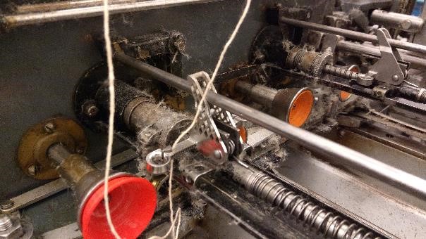
Wire guide (Oyfo)
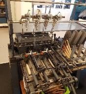
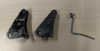
A textile machine (image below) distributes a large spool of thread over smaller wooden spools, which are used as a weaving thread in another textile machine. There are thread guides on them, which move back and forth quickly and guide the thread evenly over the wooden spools. The original wire guides are worn out because the machine has served many years and it still runs daily in the museum. The original part is made of steel sheet and connected with two bent pieces of metal wire. The part is no longer manufactured and original spare parts are no longer available. To keep the machine (rotating cultural heritage) running, a replacement part is needed.
Scanning and modeling
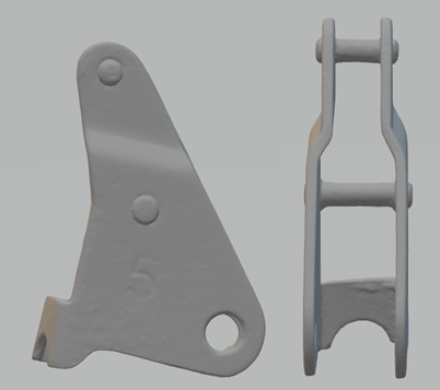
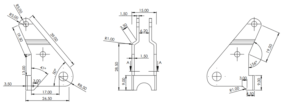
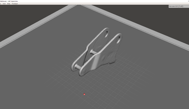
The thread guide has been scanned as it contains many different nooks and crannies. Several scanners have been tried, but the 3D scanner Artec Space Spider gave the most detailed result, shown in the image below. For comparison, the part was also measured with a caliper and retraced in SolidWorks.
Digital repairment
The wire guide has been digitally reconstructed in two ways with other software:
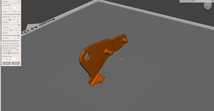
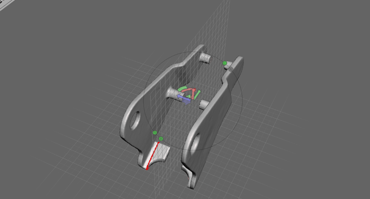
1) With Meshmixer in combination with SolidWorks:
The scan has no defined position and orientation. The part is positioned in the desired way in Meshmixer. The file was then converted to a .STL so it can be edited in SolidWorks. There, the mdoel is converted into a solid body and the holes have been given the exact size and bent surfaces have been adjusted.
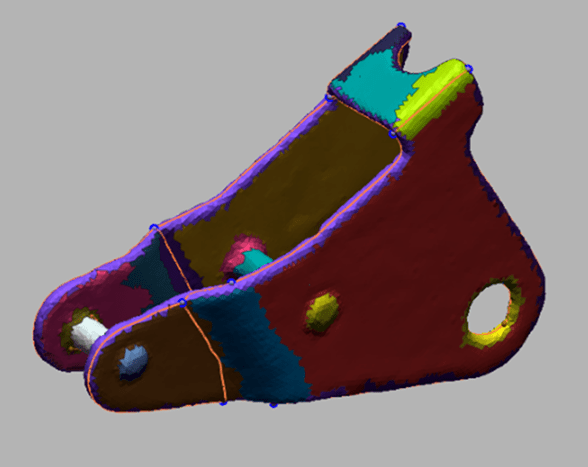
2) in Geomagic Design X:
In Geomagic Design X, the model was created using the following steps:
- Checking and improving mesh
- Select the automatic segmentation function. The software detects segments from which the model can be rebuilt into a solid. Figure 12.
- Trace contour lines into a sketch
- Make solid body to be able to make adjustments.
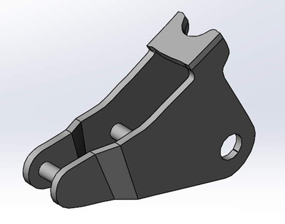
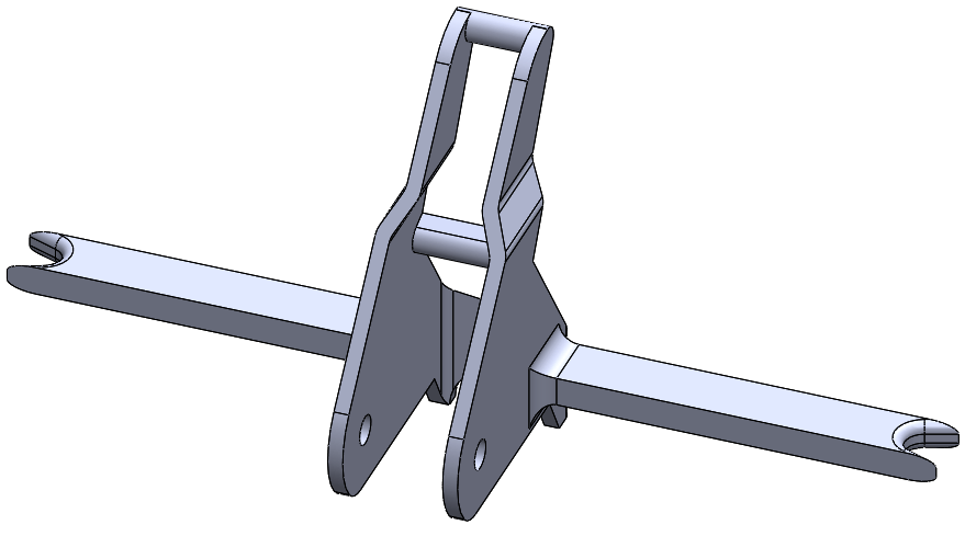
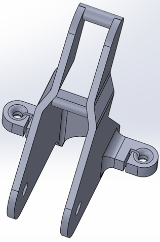
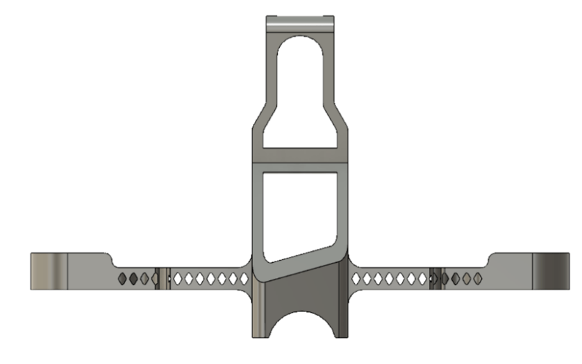
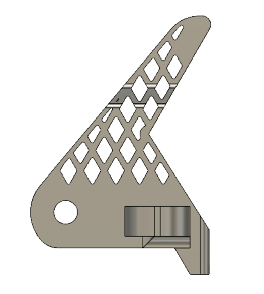
Redesign
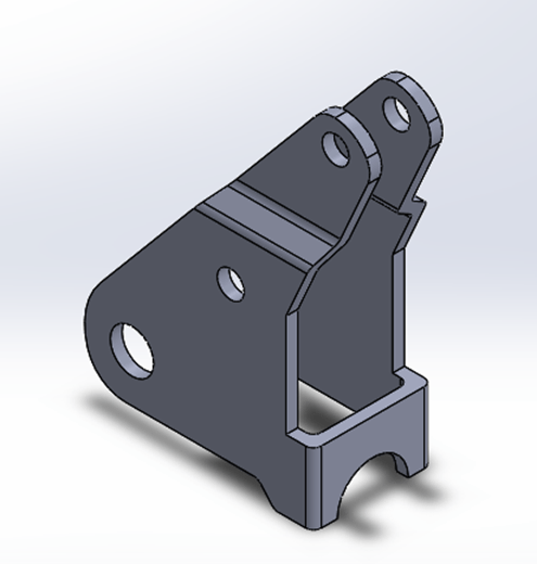
Subsequently, the product was redesigned in SolidWorks. Based on Oyfo’s requirements and the concept they had already designed themselves, the “arms” are integrated. Several iterations have been made in view of improved functionality of the wire guide.
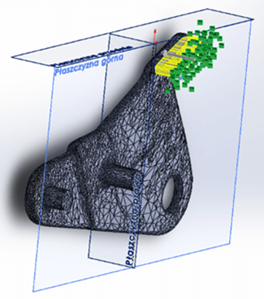
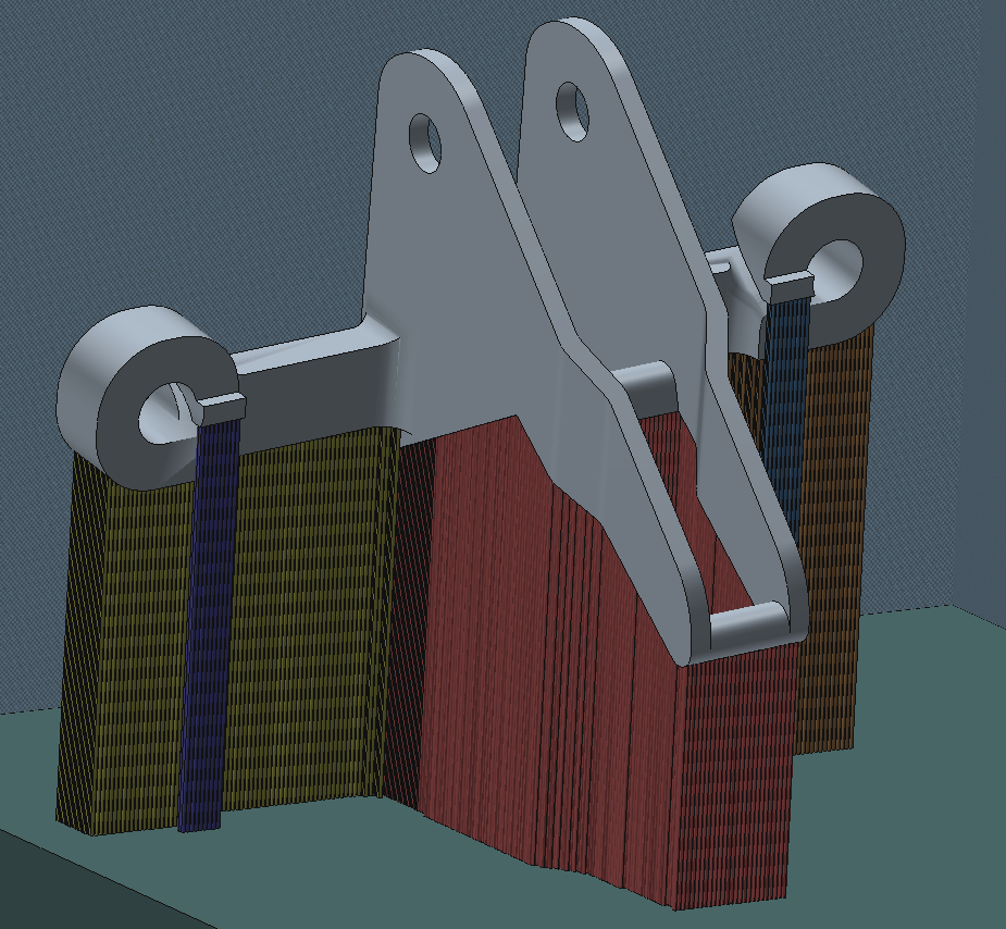
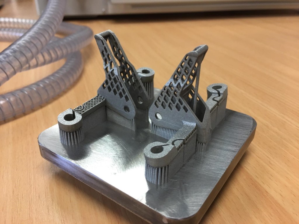
Preparation and 3D printing
Before printing, the model must be positioned on the build plate. Subsequently, support material must be applied for sufficient heat dissipation and of course to support the model itself. The models are printed in stainless steel 316L with the Concept laser Mlab Cusing SLM printer.
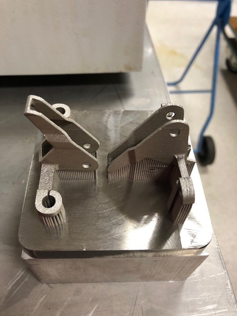
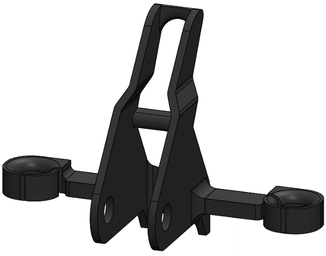
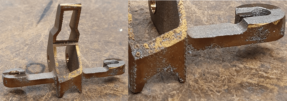
Post-processing
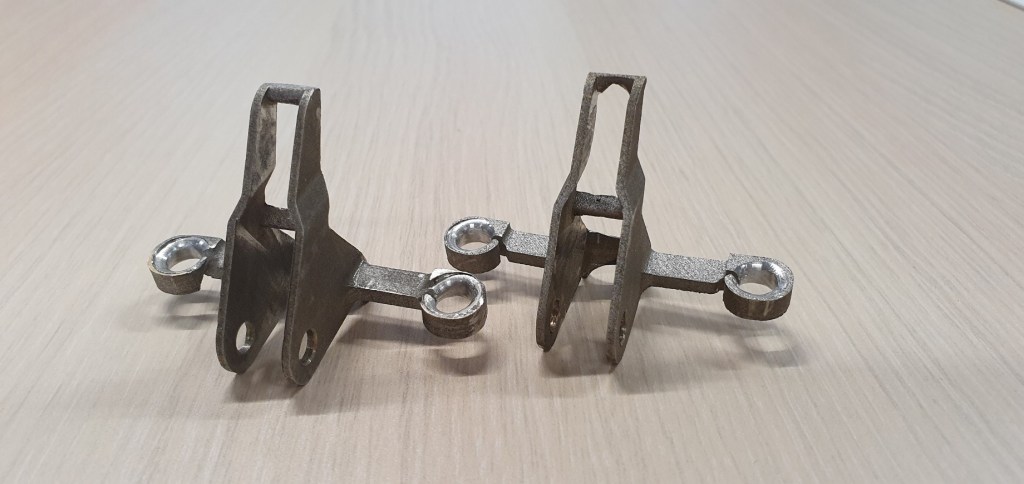
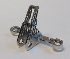
First, the excess powder is removed. After that, the parts were removed from the build plate with a water-cooled rotary saw blade. The support material was removed with a cutter. Attachments of surface support material are removed with a dremel. The models are kiln annealed for 15 minutes at 500 ° C and slowly cooled to room temperature to reduce residual stress. Three printed wire guides have been finished by Rösler: two by means of sliding grinding (4 and 8 hours) and one is electropolished (ligh-weight shiny model below).
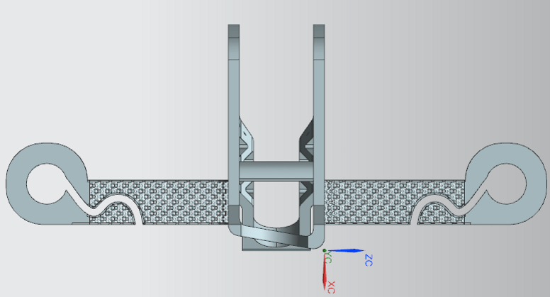
Testing
The part was returned to Oyfo museum and tested on the original mahine. Several adjustments were made to improve stress handling and smoothness of movement.